Introduction
Injection molding is a fundamental process in modern manufacturing. It evolved from traditional metal die casting and has become a highly efficient and cost - effective way to mass - produce complex thermoplastic parts. Its ability to precisely replicate intricate shapes on a large scale makes it essential in various industries, including automotive, electronics, consumer goods, and medical devices. However, the success of injection molding doesn't just depend on advanced equipment or high - quality materials; it critically relies on mold design. A well - designed mold guarantees smooth production, fewer defects, and optimal part performance. Even small design errors can lead to functional failures, production delays, or significant cost increases.
This guide focuses on 15 common injection molding design mistakes, beginning with basic geometric defects that often appear in initial designs. By analyzing their root causes, real - world impacts, and practical solutions, we aim to provide designers, product developers, and engineers with the knowledge to improve part quality, simplify manufacturing, and maximize the efficiency of thermoplastic part production.
1. Injection Mold Geometry Design Defects
The geometric design is the core of any injection mold. Problems in part geometry, such as uneven wall thickness, sharp corners, or insufficient draft angles, can disrupt material flow, cooling, and ejection, causing a series of production issues. Among these, inconsistent or improper wall thickness is one of the most common and impactful problems.
1.1 Inconsistent or Improper Wall Thickness
Definition
Inconsistent or improper wall thickness means an uneven distribution of a part's cross - sectional thickness or dimensions that don't meet the optimal range for the selected thermoplastic material. This basic geometric flaw occurs when designers focus more on part functionality than manufacturability, resulting in sudden thickness changes, overly thick sections, or areas too thin to maintain structural integrity.
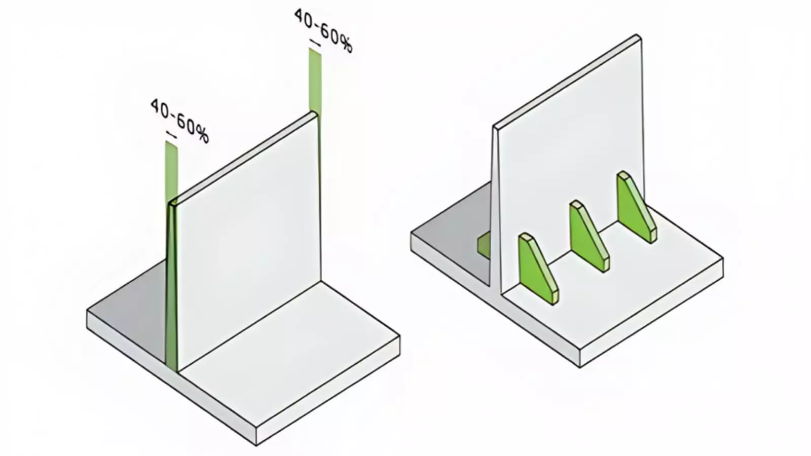
Figure 1: Example of inconsistent wall thickness (left) causing sink marks and warping, versus optimized uniform thickness (right) with smooth cooling and minimal defects.
Consequences
- Shrinkage and Sink Marks: Thermoplastics shrink as they cool, and thicker sections cool more slowly than thinner ones. This difference in cooling causes the solid outer layer of thick sections to pull inward as the inner material continues to shrink, resulting in visible depressions (sink marks) on the part surface. For example, in an ABS part, a 5mm thick rib next to a 2mm wall can create sink marks that affect the aesthetics and, in critical applications like consumer electronics, reduce the perceived quality.
- Warping and Distortion: Uneven wall thickness creates internal stresses because different regions cool at different rates. Thicker areas stay molten longer, generating residual stresses that cause the part to warp as it solidifies. A study by the Society of Plastics Engineers (SPE) found that parts with thickness variations over 25% are three times more likely to warp, with distortions ranging from 0.5mm to 2mm in small components (e.g., 50mm x 50mm plastic brackets).
- Reduced Structural Integrity: Overly thin walls may break under load, and sudden thickness changes create stress concentration points. For instance, a polypropylene (PP) part with a sudden increase from 1mm to 4mm thickness is likely to crack at the transition during assembly or use because the thin section is a weak point under tensile or impact stress.
Practical Solutions
To solve these problems, designers should prioritize wall thickness optimization from the start:
- Enforce Uniform Wall Thickness: Try to keep the thickness consistent across the part. Most thermoplastics work best within a specific thickness range:
- Adopt Gradual Transitions for Necessary Thickness Changes: When thickness variations are inevitable (e.g., for ribs or bosses), use tapers or fillets for smooth transitions. A draft angle of 1°–3° for thickness changes ensures even material flow and reduces stress concentration. For example, a rib changing from 3mm to 2mm should use a 2° taper over a 5mm length to distribute cooling and stress.
- Leverage Computer - Aided Engineering (CAE) Tools: Simulation software like Moldflow or SolidWorks Plastics can predict cooling rates, shrinkage, and warpage based on wall thickness. These tools help designers identify problem areas early, such as highlighting a 6mm thick section in a PP part as a warping risk, and adjust the geometry before mold fabrication, saving up to 30% in prototyping costs (according to data from industry consultant RJG, Inc.).
Conclusion
Mold design is crucial for successful injection molding, and geometric defects like inconsistent or improper wall thickness are among the most important issues to address early. By focusing on uniform thickness, following material - specific guidelines, and using simulation tools to validate designs, engineers can prevent costly problems like sink marks, warping, and structural failure. These strategies not only improve part quality but also simplify production, reduce rework, and ensure that thermoplastic parts meet functional and efficiency goals.
As we explore more design mistakes in future guides, remember that proactive design optimization, starting with basic elements like wall thickness, is the key to fully realizing the potential of injection molding for mass - production efficiency.